A Simple Method to Build a Programmable Oscillator
4/15/2023 6:16:32 PM
Ⅰ. How to Build a Programmable Oscillator
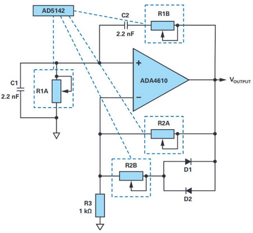
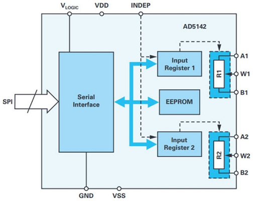
Figure 1 illustrates a typical diode-stabilized Venturi bridge oscillator that can generate a precise sine wave signal at the output with a frequency range of around 10 kHz to 200 kHz (VOUTPUT). The oscillator is made up of two bridges, one of which is a bandpass filter and the other a voltage divider. This example employs the AD5142 digiPOT, which comprises two independently adjustable potentiometers, each with 256-step resolution, in addition to the ADA4610-1 rail-to-rail precision amplifier. As demonstrated in Figure 2, the value is set via programming. The AD5142A, which is controlled by I2C, can also be used. Both 10 kΩ and 100 kΩ potentiometers are offered.

Figure. 1 Amplitude Stable Programmable Wien Bridge Oscillator in which Resistors are Replaced by digiPOTs

Figure. 2 Functional Block Diagram of AD5142
R1A, R1B, C1 and C2 form positive feedback in the traditional depicted in Figure 1, whereas R2A, R2B, and the two parallel D1 and D2 or their resistor RDIODE form a negative feedback. The formula can be utilized in this scenario:
R2 = R2A||(R2B+RDIODE)
In order to achieve continuous stable oscillation, the phase shift in the loop gain needs to be eliminated. Expressed as a formula, the oscillation frequency:
ω0 = 1/RC or f0 = 1/2πRC
where R represents the programmable resistor value on the AD5142:
R = (256-D)/256*RAB
D represents the decimal equivalent of the programmable digital code in the AD5142, and RAB represents the total resistance of the potentiometer.
The Wien bridge oscillator must be generally balanced in order to maintain oscillation, which means the positive and negative feedback gains must be synchronized. The oscillation amplitude or VOUTPUT will increase until the amplifier saturates if the positive feedback (gain) is too strong. If negative feedback takes precedence, the oscillation amplitude will decrease.
The gain R2/R1 in this circuit should be tuned to roughly 2 or greater. The signal will begin to oscillate as a result of this.
However, turning on and off the diodes in the negative feedback loop alternately reduces the gain to less than 2, stabilizing the oscillations.
Once the desired oscillation frequency is determined, the oscillation amplitude can be tuned independently of frequency via R2. It can be calculated by the following formula:
2/3VOUTPUT = ID*R2B+VD
As a result, the ID of the variable and VD denote the forward current and diode forward voltage, respectively, through D1 and D2. If R2B is shorted, the oscillation amplitude will be around ±0.6 V. An equilibrium is attained when the magnitude of R2B is of the correct magnitude, allowing VOUTPUT to converge. For R2B, a single 100 kΩ digiPOT is utilized in the circuit shown in Figure 1.
Ⅱ. Conclusion
The 8.8 kHz, 17.6 kHz, and 102 kHz oscillation frequencies can be tuned with resistance values of 8 kΩ, 4 kΩ, and 670Ω, respectively, using the specified circuit and a 10 kΩ dual digiPOT, with frequency inaccuracies as low as ±3%. The frequency error may be affected by increasing the output frequency. The frequency inaccuracy will increase to 6% at 200 kHz, for example.
When using such circuits in frequency-dependent applications, it's important not to exceed the digiPOT 's bandwidth limit, which is determined by the programmable resistance. Furthermore, the frequency tuning depicted in Figure 1 necessitates the use of the same and R1B resistor values. The two channels, on the other hand, can only be set in order, resulting in a temporary critical intermediate state. This scenario is unacceptable for some applications. A digiPOT that supports daisy-chain mode, such as the AD5204, can be used in these circumstances to modify the resistor values at the same time.
Related Information
-
Whatsapp

-
Email
-
Tel
86-13590266466


